Why the Buzzer Does Not Sound and Buzzer Failure Analysis
The buzzer is a common electroacoustic device with the advantages of being simple, compact, small size, lightweight, and low cost. The buzzer in the circuit graphic symbol the letter “H” or “HA”.
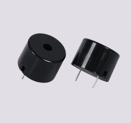
The buzzer is a common device in circuit design, widely used in industrial control, room monitoring, access control, computer, and other electronic products as a warning sound device. However, many people tend to design randomly, resulting in actual circuits where the buzzer is not audible, slightly audible, and messy.
Buzzer Common Failures and Analysis
Buzzer failures are usually as follows.
The buzzer does not sound before installation, this is the quality issue of the buzzer.
The buzzer after welding no sound or when the sound does not sound, this situation may be used in the welding process of the soldering iron power is too large recommended 20-30W iron or too long recommended 3 seconds to complete a soldering point resulting in the buzzer pin and the coil of the soldering point melted by heat after the false solder.
After welding the buzzer beeping process out of a small sound, no sound or sand tone change, this situation may be to start the buzzer current is too small or too large than buzzer normal operating current 20-30mA resulting in the buzzer can not be normal beeping.
After using the buzzer for a period of time, there is a change of sound or no sound. This situation may be due to the continuous sounding time of the buzzer is too long the continuous sounding time of the buzzer cannot exceed 8-10 hours, otherwise, it will change or burn out or the buzzer is affected by the environment.
The buzzer soldered in the wire board work when there is a change of tone or no sound, but remove the DC voltage regulator test is no problem, this situation may be the buzzer interference.
Circuit Analysis
The following is the EasyARM-i.MX283 development kit, on the 3.3V NPN transistor, drives active buzzer design, from the actual product to analyze the circuit design problems, circuit improvement program, learn to analyze and improve the circuit method, so as to design a better product, to achieve the effect of throwing bricks to draw jade.
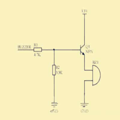
The above diagram is a typical wrong connection when the buzzer terminal input is high which will result in that the buzzer does not sound or the sound is too small. When the I/O port is high, the base voltage is 3.3/4.7*3.3V≈2.3V, due to the voltage drop of the transistor 0.6~0.7V, the transistor emitter voltage is 2.3-0.7=1.6V, the drive voltage is too low resulting in the buzzer not being driven or the sound is very small.
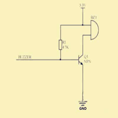
The diagram above shows the second typical wrong connection, due to the pull-up resistor R2, BUZZER terminal in the output low level, due to the voltage dividing effect of resistors R1 and R2, the transistor can not be reliably turned off.
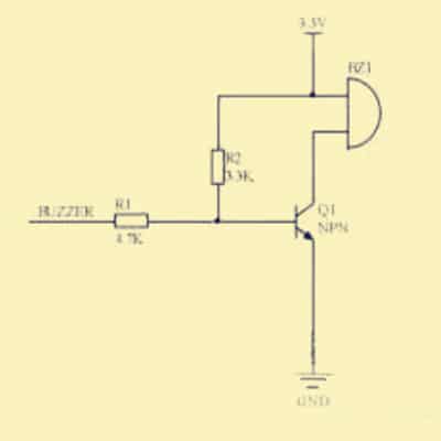
The above figure is the third wrong connection, the transistor’s high-level threshold voltage is only 0.7V, that is, the input voltage at the BUZZER terminal as long as more than 0.7V may make the transistor conductive, obviously, 0.7V threshold voltage for the digital circuit is too low, in the environment of electromagnetic interference, it is easy to cause the buzzer chirp.
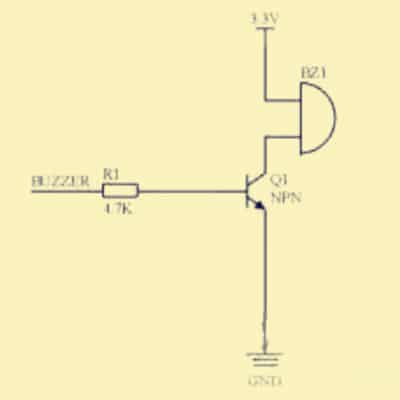
The above figure is the fourth wrong connection, when the CPU GPIO pin there is an internal pull-down, due to the I/O port input impedance, which may also lead to the transistor can not be reliably turned off, and the third as long as the buzzer terminal input voltage exceeds 0.7V may make the transistor conductive.
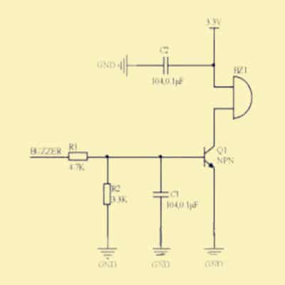
The diagram above shows the NPN triode control active buzzer conventional design drive circuit for a universal active buzzer. Resistor R1 is a current limiting resistor to prevent excessive current flowing through the base from damaging the transistor. Resistor R2 has an important role, the first role, R2 is equivalent to the pull-down resistor of the base, if the input is left open, the presence of R2 can keep the transistor in a reliable off state.
If R2 is removed when the buzzer input is left open, it is susceptible to interference and may cause the transistor state to flip unexpectedly or enter an undesired amplification state, causing the buzzer to sound unexpectedly. The second role, R2 can raise the threshold voltage of the high level. If R2 is removed, the high-level threshold voltage of the transistor is only 0.7V, that is, the input voltage at the A-side is likely to conduct as long as it exceeds 0.7V. The situation is different when R2 is added when the input voltage from the A-side reaches about 2.2V before the transistor saturates and conducts, in which C2 is the power supply filter capacitor to filter out high-frequency clutter from the power supply. C1 can effectively filter out interference signals in an environment with strong interference C1 can effectively filter out the interference signal in a strong interference environment to avoid the buzzer from changing its tone and accidental sounding. In the RFID RF communication, Mifare card applications, here the initial choice of 0.1uF capacitor, the specific can be selected according to the actual situation.


